Fault Slip

Fault Slip
The Map3D CAD interface has numerous features to make model building fast and easy. The newest of these features is the trace command. To tabular mining layout illustrated below can be built quite easily with this feature. We would first import some mine plans. These particular planes are in PNT format. Map3D can import DXF (AutoCAD drawing exchange format) and PNT (simple pen-up/pen-down format) files or digitize drawings directly from plans.
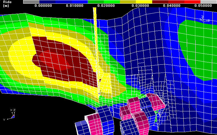
This problem shows the ride on a waving fault plane that intersects some 3D mining blocks and a mine shaft. The analysis was run to study offsetting in the shaft do to the non-linear slip on the fault. Multiple mining steps were considered to determine how the slip progressed with advancing mining.
The fault is constructed with a series of DD (displacement discontinuity) elements that are used to simulate discrete slip. The gouge material in the fault has been assigned a Mohr-Coulomb strength criterion and thus only slips where the shear stresses exceed the frictional strength.
The mining excavations and the shaft are constructed with FF (fictitious force) elements. Note that the intersections between the fault, mining and shaft were constructed automatically by Map3D during the preprocessing analysis stage.
The model was constructed with 30 3D FF blocks and 38 DDs. From this data, Map3D generated 542 surfaces and subsequently discretized these into 2401 boundary elements, thus requiring 7203 degrees of freedom. Due to efficient lumping, the matrix size required for this analysis was only 33 MBytes.
Sample Code
This entire operation can easily be completed in well under one minute.
zipped example contains contains the analysis results pictured above.
Download Example- Unzip testw41.zip to create testw41.001
- To display these results in Map3D, use File > Open Analysis Results and select testw41.001
- To display the ride on the fault use Plot > Surface Components > Ride.
