Easy construction of tabular mining
Easy construction of tabular mining
The Map3D CAD interface has numerous features to make model building fast and easy. The newest of these features is the trace command. To tabular mining layout illustrated below can be built quite easily with this feature. We would first import some mine plans. These particular planes are in PNT format. Map3D can import DXF (AutoCAD drawing exchange format) and PNT (simple pen-up/pen-down format) files or digitize drawings directly from plans.
Sample Code
This entire operation can easily be completed in well under one minute.
PDF example contains a demonstration of building the mine plans pictured above
Download Example- Unzip t.zip to create t.pnt
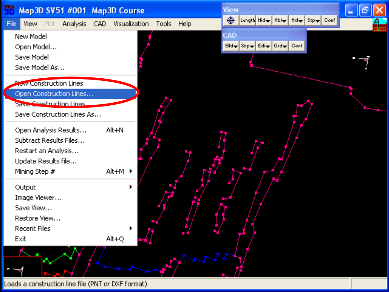
- To display these construction lines in Map3D, use File > Open (Construction Lines) and select t.pnt
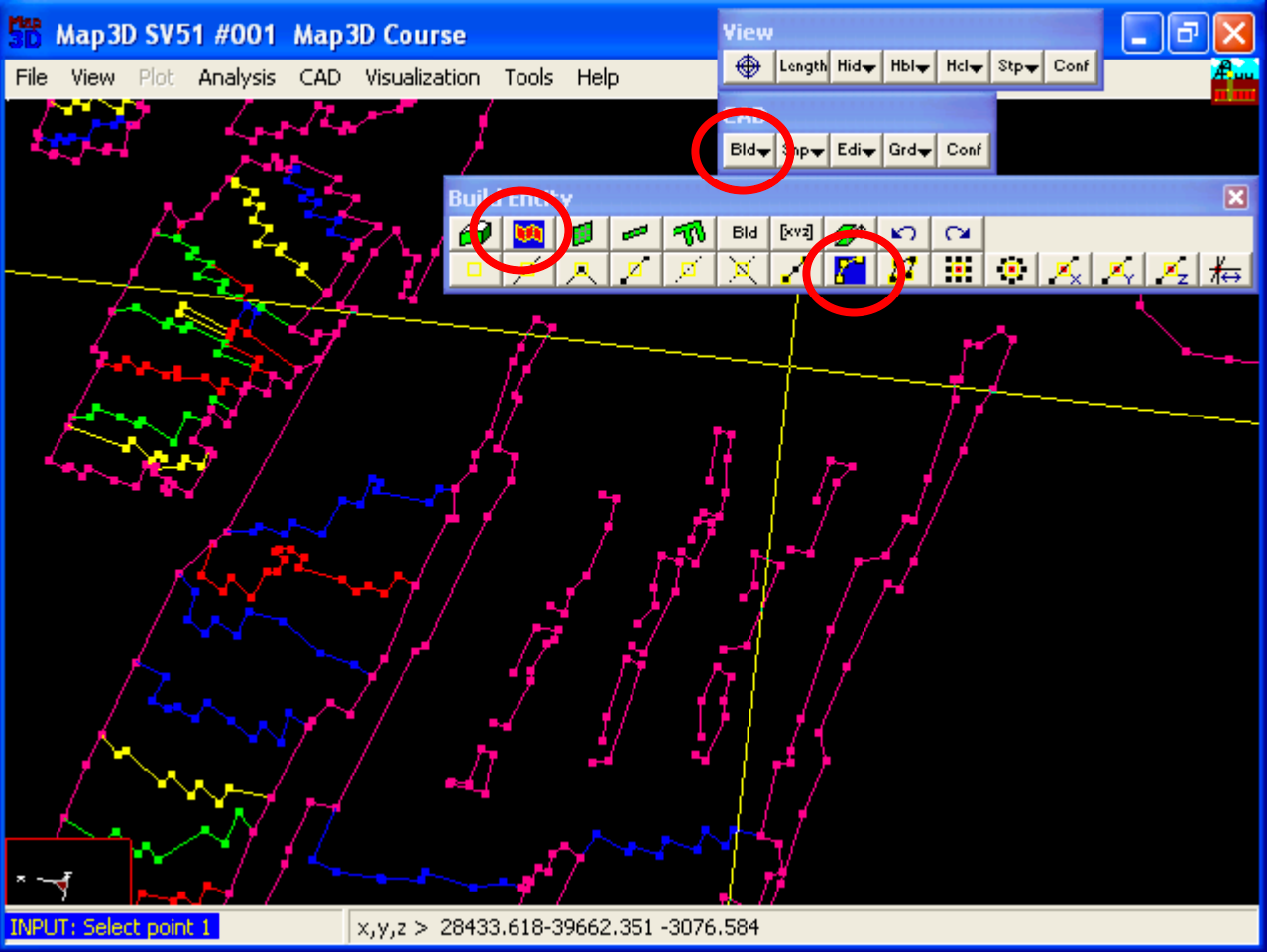
- Begin building the floor plan, using CAD > Build > DDLoop.
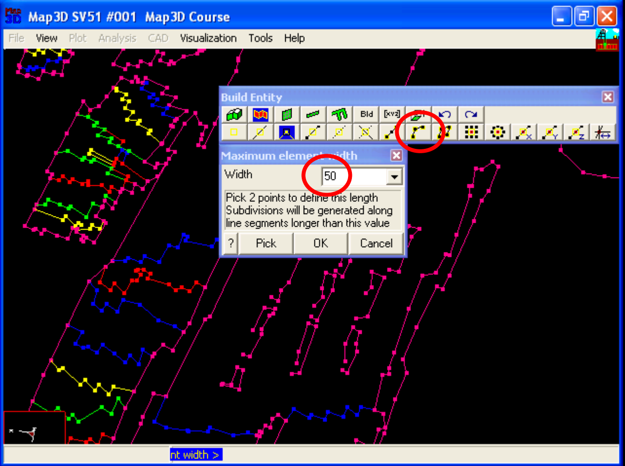
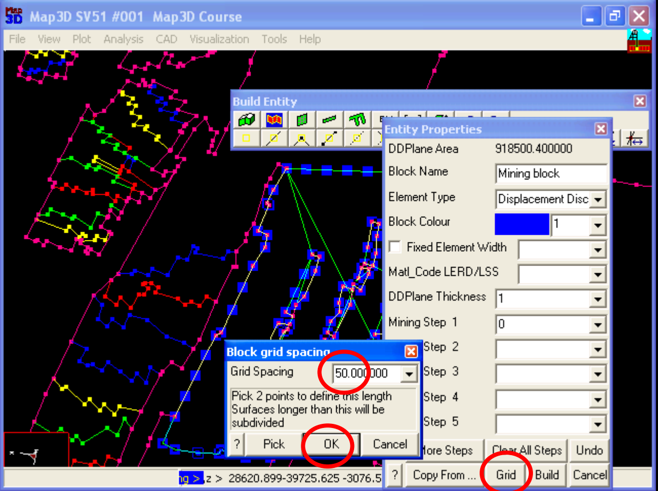
- Enable trace snapping by selecting CAD > Snap > Trace Snap. Specify the maximum element width as 0. Select OK.
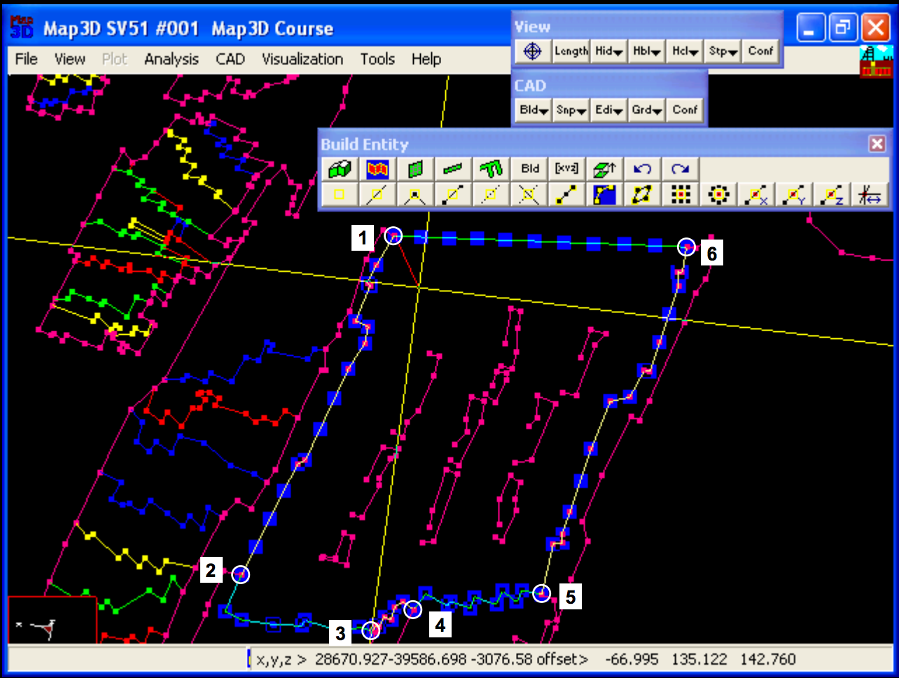
- Select the points on the construction lines to define a perimeter loop, as illustrated above.
- Close the loop by selecting the first point again.
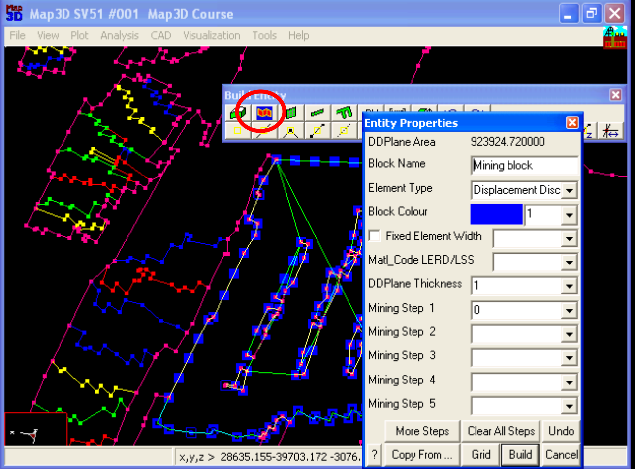
- From the entity properties dialogue box, specify the desired colour then select Build.
- Select YES when asked if you want to trace around interior loops.
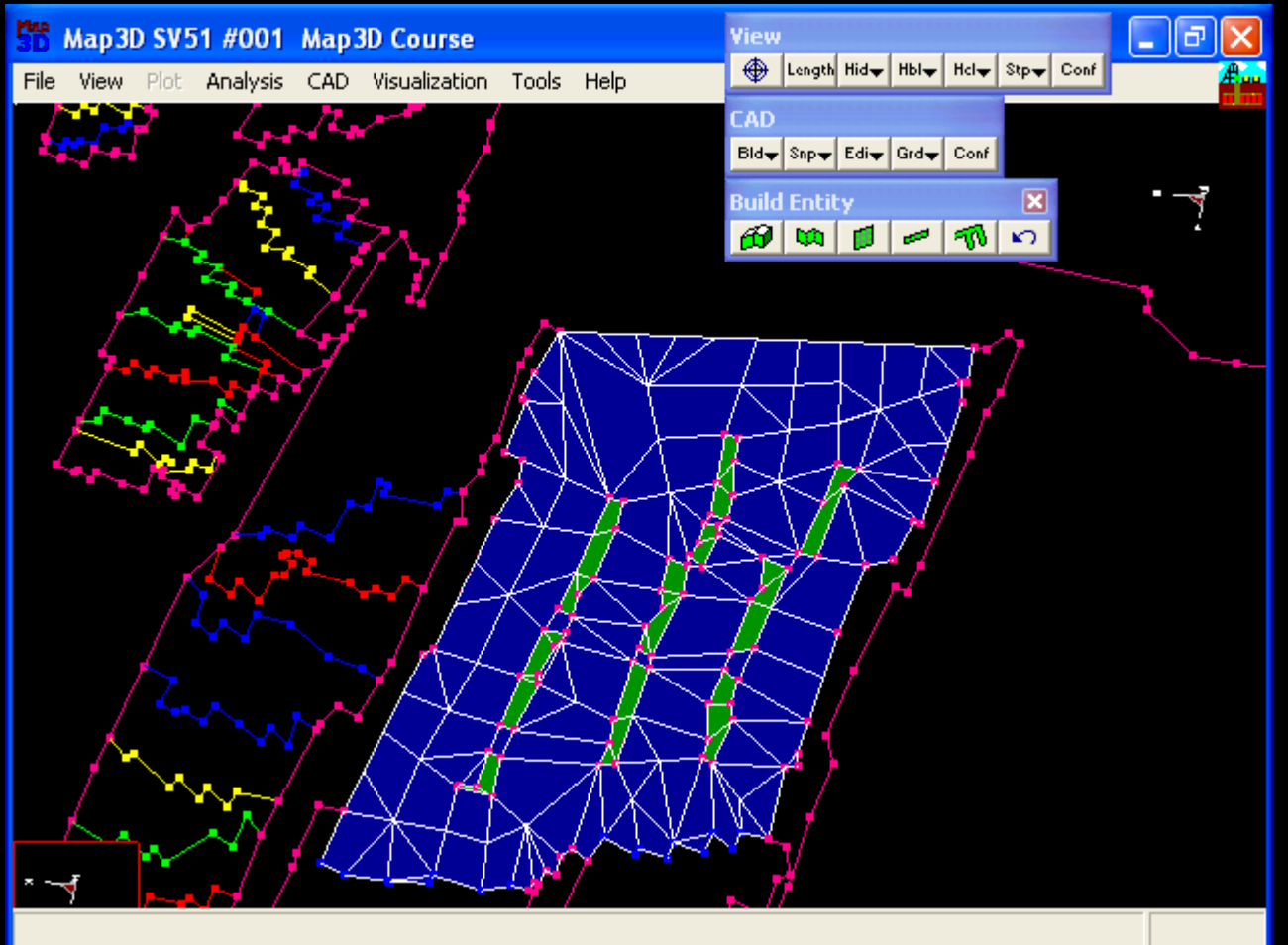
- The elements within the loop will now be constructed.
Construction of Dyke
- To construct the dyke, trace the loop around the floor plan of the dyke as above.
- Close the loop by selecting the first point again.
- From the entity properties dialogue box, specify the desired colour.
- Now change the element type to Fictitious Force. Specify the block extrusion vector as (100,200,500). Select OK.
- To copy the upper part of the dyke below the plane of the mining, use CAD > Edit > Copy Entities.
- Change the selection mode to Select by Colour.
- Double click on the dyke, and specify (-100,-200,-500) as the copy offset vector. Select OK.