Map3D uses several different, but complimentary strategies to permit analysis of very large problem sizes. Discretization is controlled such that boundary elements are only used in locations where they are needed. Several forms of lumping are then used to reduce analysis time and disk space requirements. Together, these features enable Map3D to accommodate very large problem sizes (more than 2,000,000 elements) on PC platforms.
Without lumping, a 64000 element problem would take 147 GB of disk space. With lumping, this can be reduced to less than 1 GB. The time required for analysis reduces by approximately the same proportion. This permits users to specify existing mining geometry in detail, and add new mining as required. This greatly reduces the effort required to set up and run analyzes and permits the whole mine to be considered when necessary.
All discretization and lumping parameters are expressed in terms of a distance over length ratio. In all cases the distance is measured between two points of interest (e.g. from one element to another, or from an element to the nearest grid point). In this ratio, the length is the size of the element, or grid spacing at one of the points of interest.
Suggested values for the discretization and lumping parameters are as follows:
•AL should be set equal to twice the smallest pillar or stope width. Use the same units used to specify the coordinates (e.g. metres or feet).
•AG should be set equal to the smallest dimension of interest. Use the same units used to specify the coordinates (e.g. metres or feet).
•![]() DON=0.5, DOL=DOC=1, DOE=DOG=2 for 10-20% error
DON=0.5, DOL=DOC=1, DOE=DOG=2 for 10-20% error
•![]() DON=0.5, DOL=DOC=2, DOE=DOG=4 for 5-10% error
DON=0.5, DOL=DOC=2, DOE=DOG=4 for 5-10% error
•![]() DON=1.0, DOL=DOC=4, DOE=DOG=8 for < 5% error
DON=1.0, DOL=DOC=4, DOE=DOG=8 for < 5% error
These parameters are set using the CAD > Properties > Control Parameters dialogue.
The details of the use of these parameters for control of discretization and lumping are described below.
DON and AL - Matrix Conditioning
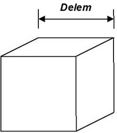
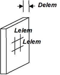
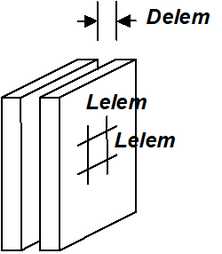
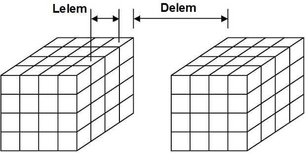
During the discretization process all model surfaces (surfaces of FF blocks and DD planes) are subdivided into boundary elements with side length
Lelem = Delem/DON
where Delem is determined by Map3D as the smallest distance between adjacent model surfaces. Since at some locations the distance Delem may be zero, the minimum element side length AL must be specified.
AL should be set equal to twice the smallest pillar or stope width. The same units used to specify the coordinates should be used (e.g. metres or feet).
A value for DON of 0.5 is generally adequate for all problems except those with very narrow excavations or pillars. In this latter case a value for DON of 1.0 is recommended.
Although higher values of DON results in generation of more boundary elements and hence longer run times, this is necessary to obtain a well-conditioned solvable problem for very narrow excavations or pillars.
DON controls the way block surfaces are discretized into boundary elements. This parameter along with AL, is used to ensure that a well-conditioned, solvable coefficient matrix will be generated by the Boundary Element Analysis.
Matrix conditioning can be directly related to the magnitude of DON. A well-conditioned, easily solved matrix can be guaranteed by using larger values (near one) of DON.
DON = 0.5
DON = 1.0
These parameters control how fine the discretization will be for surfaces, which pass near one another. For example comparing examples using DON of 0.5 and 1.0, it can be observed that larger values of DON produce smaller boundary elements where the stope is locations.
From an analysis point of view, there are three basic types of problems. The easiest to solve are problems, which use bulky, three-dimensional shapes such, that surfaces are spaced well apart.
For this type of problem, a well-conditioned coefficient matrix will always be generated, and the effect of DON and AL are not important.
The next most difficult type of problem to solve is one where narrow stopes are defined. For this case, the distance Delem (which is the smallest distance from one element to another) is just the stope width. Since the element side length Lelem can be calculated from the DON ratio as
Lelem = Delem/DON
such that Lelem is not less that AL, small values of DON will generate small elements only near locations where stopes are narrow. As one moves away from these areas, the element size will very quickly increase. The use of fictitious force elements to create this type of tabular shaped excavation can result in a poorly conditioned matrix unless a value of DON of approximately one half is used. This must of course be accompanied by a sufficiently small value of AL to permit small elements to be generated.
AL should normally be set equal to the width of the narrowest pillar, stope, or the smallest hangingwall to footwall distance. This will permit the discretization routine to use as small size elements as are necessary to ensure proper matrix conditioning.
The most difficult type of problem to solve is one where narrow pillars are defined or where narrowly spaced joints are used. As above, Delem is the stope or pillar width. The element side length can also be calculated from the DON ratio, however, for this type of problem, where excavations are very near one another, creating narrow pillars, a poorly conditioned unsolvable matrix will be created unless a value of DON of approximately one is used. This must of course be accompanied by a sufficiently small value of AL to permit small elements to be generated.
The recommended value of DON is 0.5 for narrow stopes problems and 1 for narrow pillar problems.
AL should normally be set equal to the width of the narrowest pillar or the smallest hangingwall to footwall distance. This will permit the discretization routine to use as small size elements as are necessary to ensure proper matrix conditioning.
In summary, AL should be set equal to the width of the narrowest pillar or the smallest hangingwall to footwall distance. Larger values may be necessary if too many elements are generated. DON should be set to 0.5 for normal problems, and 1.0 for problems where narrow pillars are defined.
During discretization, Map3D will attempt to satisfy the specified DON ratio for all elements. When discretizing, the maximum number of boundary elements that any block or plate edge can be divided into is 256. If this number of subdivisions is reached, and the specified DON ratio has still not been achieved, Map3D will issue a warning message instructing the user to subdivide the block or plate into smaller pieces.
Once discretization is complete, the distance Delem can be plotted using
![]() Plot > Miscellaneous > Delem Distance to nearest element on surfaces
Plot > Miscellaneous > Delem Distance to nearest element on surfaces
The ratio of Delem/Lelem can be plotted using
![]() Plot > Miscellaneous > Delem/Lelem DON ratio on surfaces
Plot > Miscellaneous > Delem/Lelem DON ratio on surfaces
Locations where DON is small (less than 0.5) could result in a non-convergent solution process.
Note that if desired, this behaviour can be overridden on an element by element basis my specifying the maximum width for each element
![]() CAD > Edit > Entity Properties > Maximum Width
CAD > Edit > Entity Properties > Maximum Width
DOL and AG - Solution Accuracy
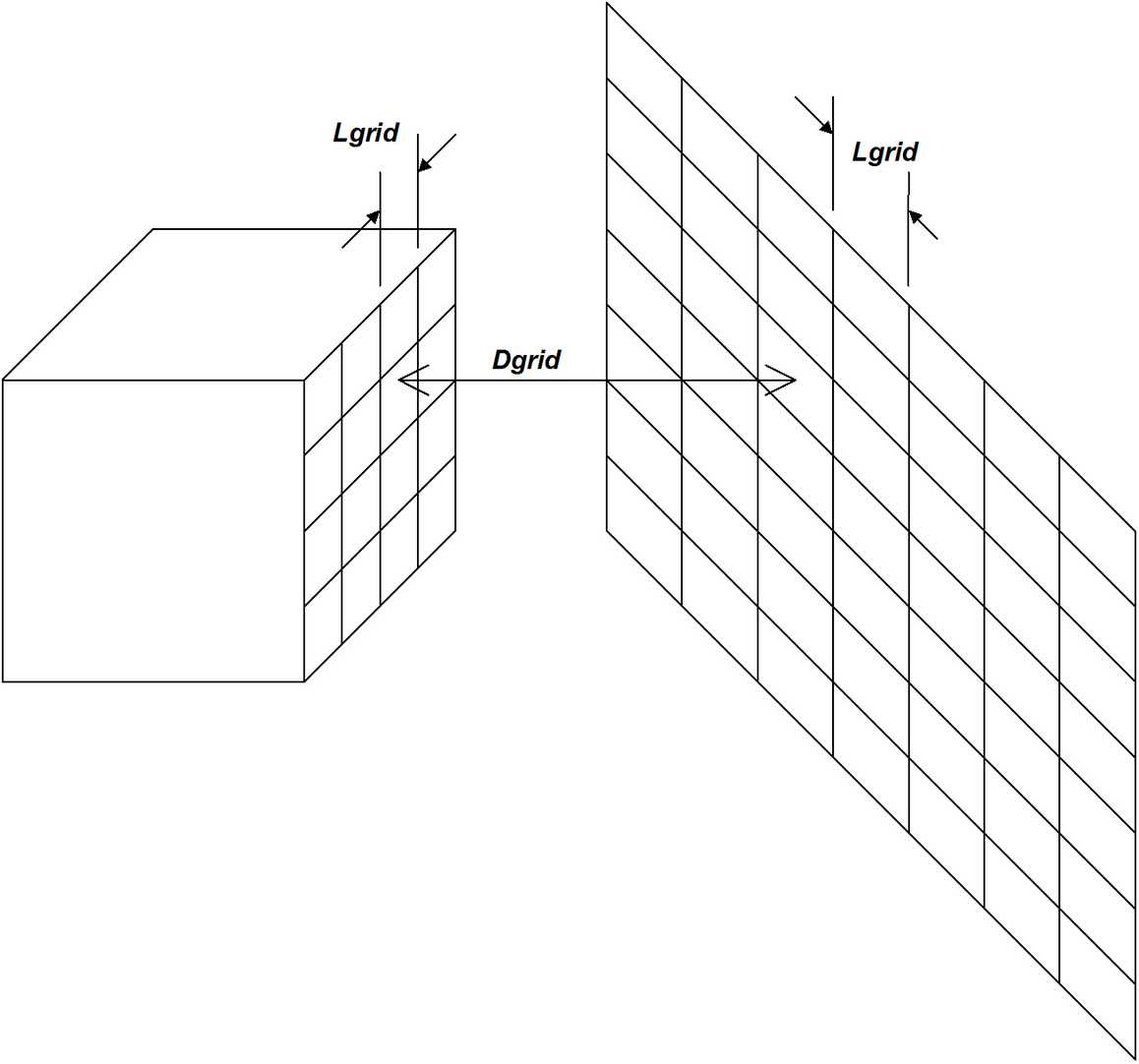
During the discretization process Blocks and DD planes are subdivided into boundary elements with side length Lgrid. The element size is determined from the minimum distance Dgrid to the nearest field point grid plane according the relation
Lgrid = Dgrid/DOL
Since at some locations the distance Dgrid may be zero, a minimum element side length AG must also be specified.
This same relationship is also used to subdivide grid planes into points where field stresses, strains and displacements are calculated. A minimum grid spacing of half AG will be used.
The AG parameter should be set equal to smallest dimension of interest. To obtain reasonable accurate results, AG should be set to approximately one quarter the stope or pillar width. For example if the user wants to see the stress distribution across a 2m wide pillar, a value of 0.5 for AG would give a sufficient number of field points for accurate contouring.
The same units used to specify the coordinate locations should be used (e.g. metres or feet).
A value for DOL of 1.0 is recommended for all problems except those where increased accuracy is required. With a value of 1.0 an error of 10-20% can be expected. A value of 2.0 should provide 5-10% error. A value of 4.0 should provide less than 2% error.
Although higher values for DOL result in more elements being generated, this is necessary to obtain increased accuracy.
DOL controls the way in which grids and block surfaces are subdivided. This parameter along with AG, is used to control the amount of detailed accuracy one requires in the results.
AG should be selected to reflect the size of interest. For example, if details of the stress distribution are only required to within one metre of the surface excavations, then AG should be set equal to one metre.
The field point spacing and element side length Lgrid, are determined from the specified DOL ratio. Dgrid is determined as the minimum distance from a given element to the nearest grid. Since Lgrid can be calculated from the DOL ratio as
Lgrid = Dgrid/DOL
such that Lgrid is not less that AG, small values of DOL will generate small elements and grid spacing only near locations where grids pass near to stopes. As one moves away from these areas, the element size will very quickly increase.
DOL = 1
DOL = 2
DOL = 1
DOL = 2
Small values of DOL (one or less) will generate small field point spacings and small elements only near locations where the grid intersects or passes very close to the block. As one moves further away from these areas, the field point spacing and element side length will very quickly increase. Larger values of DOL (two or more) will increase the distance over which the field point spacing and element side length are kept small.
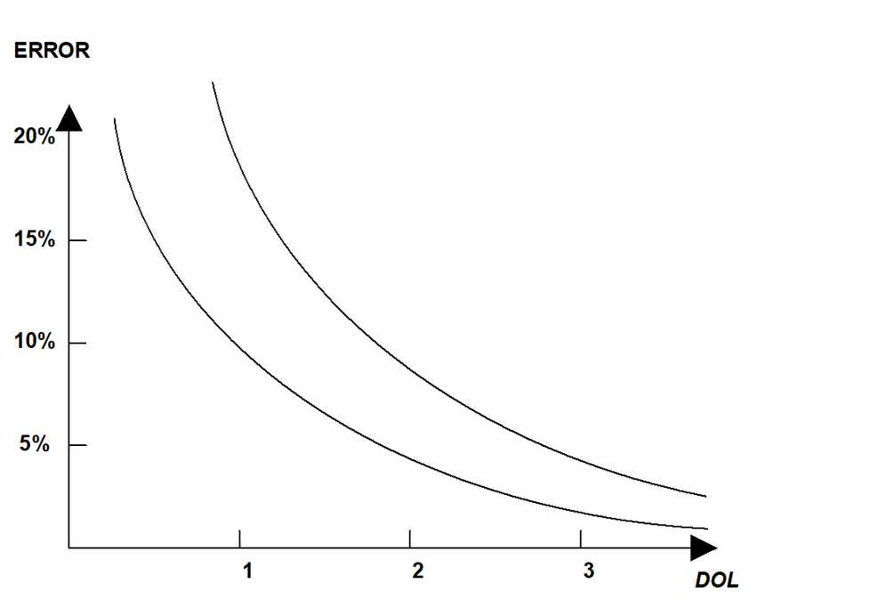
Result accuracy can be directly related to the magnitude of DOL. Errors are limited to approximately 10-20% for DOL near one, and 5-10% for DOL near two. These values are only approximate, and it is therefore recommended that in problems where high accuracy is required, values of DOL near four be used. In problems where low accuracy is necessary, DOL near one is adequate. It is not recommended to set DOL less that one.
Note that large values of DOL and small values for AG result in increased number of elements and increased run times, but greater accuracy.
In summary, AG should be set to the resolution of interest (a fraction of the stope width). DOL should be set to 1 for coarse analysis results, 2 for detailed analysis results, and 4 when very high accuracy is required.
During discretization, Map3D will attempt to satisfy the specified DOL ratio for all elements and grids. When discretizing, the maximum number of boundary elements that any block or plate edge can be divided into is 256. The maximum number of field points that any grid edge can be divided into is also 256. If this number of subdivisions is reached, and the specified DOL ratio has still not been achieved, Map3D will issue a warning message instructing the user to subdivide the block, plate or grid into smaller pieces.
Once discretization is complete, the distance Dgrid can be plotted on model surfaces using
![]() Plot > Miscellaneous > Dgird Distance to nearest grid on surfaces
Plot > Miscellaneous > Dgird Distance to nearest grid on surfaces
or on grids using
![]() Plot > Miscellaneous > Dgrid Distance to nearest element on grids
Plot > Miscellaneous > Dgrid Distance to nearest element on grids
The ratio of Dgrid/Lgrid can be plotted on model surfaces using
![]() Plot > Miscellaneous > Dgrid/Lgrid DOL ratio on surfaces
Plot > Miscellaneous > Dgrid/Lgrid DOL ratio on surfaces
or on grids using
![]() Plot > Miscellaneous > Dgrid/Lgrid DOL ratio on grids
Plot > Miscellaneous > Dgrid/Lgrid DOL ratio on grids
Note that if desired, this behaviour can be overridden on a grid by grid basis by specifying the maximum width for each grid
![]() CAD > Edit > Entity Properties > Maximum Width
CAD > Edit > Entity Properties > Maximum Width
DOR - Element Aspect Ratio
DOR controls the maximum element aspect ratio. If the ratio of the side length of an element is determined to exceed DOR, that element is subdivided. The recommended value of DOR is 5. If erratic results are detected, DOR should be decreased to 2. Note that smaller values of DOR results in more elements and longer run times, but greater accuracy.
During discretization, Map3D will attempt to satisfy the specified DOR ratio for all elements. When discretizing, the maximum number of boundary elements that any block or plate edge can be divided into is 256. If this number of subdivisions is reached, and the specified DOR ratio has still not been achieved, Map3D will issue a warning message instructing the user to subdivide the block or plate into smaller pieces.
DOC - Matrix Lumping
During matrix assembly, the distance Delem between groups of Blocks and DD planes is examined to see if these can be lumped together for calculation and storage purposes. The amount of lumping depends on how many elements can fit into a zone with side length Lelem, determined from the relation
Lelem = Delem/DOC
A value for DOC of 1.0 is recommended for all problems except those where increased accuracy is required. With a value of 1.0 an error of 10-20% can be expected. A value of 2.0 should provide 5-10% error. A value of 4.0 should provide less than 5% error.
Although higher values of DOC result in larger problem sizes, this is necessary to obtain increased accuracy.
DOC controls the way in which elements are lumped during matrix assembly. Elements with combined side length Lelem, are lumped if the distance Delem, to the affected element exceeds the required DOC ratio. If the stope to stope distances are large, many elements can be lumped.
Small values of DOC (one or less) will provide maximum lumping, however, stresses near excavation surfaces will deteriorate in accuracy, and matrix conditioning will be reduced. Larger values of DOC (two or more) will provide less lumping, but accuracy and good matrix conditioning will be maintained.
DOC should be set to 1 for coarse analysis results, 2 for detailed analysis results, and 4 when very high accuracy is required. Note that large values of DOC results in increased matrix size and longer run times, but greater accuracy.
DOE - Element Lumping
During the calculation of field points (i.e. grid assembly), the distance Dgrid between these points and groups of Blocks and DD planes is examined to see if these groups can be lumped together for calculation purposes. The amount of lumping depends on how many elements can fit into a zone with side length Lgrid, determined from the relation
Lgrid = Dgrid/DOE
A value for DOE of 2.0 is recommended for all problems except those where increased accuracy is required. With a value of 2.0 an error of 10-20% can be expected. A value of 4.0 should provide 5-10% error. A value of 8.0 should provide less than 5% error.
Although higher values of DOE result in larger analysis times, this is necessary to obtain increased accuracy.
DOE controls the way in which elements are lumped during field point calculations. Elements with combined side length Lgrid, are lumped if the distance Dgrid, to the field point exceeds the required DOE ratio. Small values of DOE (two or less) will provide maximum lumping, however, stresses distributions near excavation surfaces will deteriorate in accuracy and become erratic. Larger values of DOE (four or more) will provide less lumping, but accuracy and smooth stress distributions will be ensured.
DOE should be set to 2 for coarse analysis results, 4 for detailed analysis results, and 8 when very high accuracy is required. Note that large values of DOE results in increased matrix size and longer run times, but greater accuracy.
DOG - Grid Lumping
During the calculation of field points (i.e. grid assembly), the distance Dgrid between these points and groups of Blocks and DD planes is examined to see if these field points can be lumped together for calculation purposes. The amount of lumping depends on how many field points can fit into a zone with side length Lgrid, determined from the relation
Lgrid = Dgrid/DOG
A value for DOG of 2.0 is recommended for all problems except those where increased accuracy is required. With a value of 2.0 an error of 10-20% can be expected. A value of 4.0 should provide 5-10% error. A value of 8.0 should provide less than 5% error.
Although higher values of DOG result in larger analysis times, this is necessary to obtain increased accuracy.
DOG controls the way in which field points are lumped during field point calculations. Field points with combined spacing length Lgrid, are lumped if the distance DOG, to the affecting element exceeds the required DOG ratio. Small values of DOG (two or less) will provide maximum lumping, however, stresses distributions near excavation surfaces will deteriorate in accuracy and become erratic. Larger values of DOG (four or more) will provide less lumping, but accuracy and smooth stress distributions will be ensured.
DOG should be set to 2 for coarse analysis results, 4 for detailed analysis results, and 8 when very high accuracy is required. Note that large values of DOG results in increased matrix size and longer run times, but greater accuracy.