![]() CAD > Edit > Entity Properties
CAD > Edit > Entity Properties
|
|
Top Previous Next |
|
Edit block type, colour, mining sequence etc.
This routine can be initiated either by picking the When you initiate this routine you will first be prompted to build a list of entities that you wish to edit
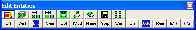
•If Tools > Shift-key Selection is checked, you must hold down the Shift-key to make multiple selections. •By default, selected entities are added to the list, however if the Ctrl-key is held down, selected entities will be removed from the list. •While holding down the Shift-key or Ctrl-key, you can drag open a crossing window. •Use of this toolbar is detailed in Build A List of Entities for Editing •Pressing the space-bar automatically activates the last edit function that was used. •Holding the Alt-key when you right-click automatically repeats the last edit function that was used.
Once you have selected the desired entities, you can either pick any of the edit buttons:
•double click on any vertex to execute the highlighted function, •right click for a list of options.
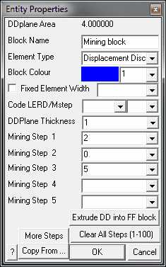
If any of the fields in the dialogue box read "Variable" it is because some of the blocks you have selected have different properties for that field. If you wish to leave these properties as they are (i.e. different for each block), leave the field as "Variable". If you wish to change the value of that field for all selected blocks, enter the desired value.
Block Volume - If you have selected all FF blocks, the total combined volume of the blocks will be displayed. If you have selected all FF blocks, the total combined volume of the blocks will be displayed.
DDPlane Area - If you have selected all DD blocks, displays the combined area of all of the DDPlanes included in the DDLoop.
Block Name - specifies a descriptive name for the block.
Element Type - specifies the type of boundary element that will be used for the block. • Displacement Discontinuity - DD type elements should be used for tabular mining excavations, fractures and fault planes. •Fictitious Force - FF type elements should be used for three-dimensional features such as excavations, alternate material zones, back-filled stopes etc. •Inactive elements can be used to display features that are to be included for visualization purposes only and not to be used for the actual stress analysis. •Note that DD type elements can be changed into GPlanes.
Block Colour - specifies the colour number that will be used to display the block. • Specifies the colour number that will be assigned to each button. A total of 10 colours are available for display. These are numbered respectively 1 through 10, 11 through 20, 21 through 30, etc., • such that the same colour is displayed for numbers 1, 11, 21..., 2, 22, 32..., 3, 23, 33..., etc.
Fixed Element Width - specifies the user defined element width. • This parameter can be used to force uniform discretization on selected entities. Extreme caution should be used in specifying this value since a small value can easily lead to enormous problem size. • In general this option should not be used (unchecked) and discretization should be left to the AL and AG parameters. These latter parameters will concentrate elements only where analysis results are requested thus optimizing the use of elements and minimizing problem size. For further discussion refer to
CAD > Properties Control Parameters
•This parameter can also be used to avoid making surfaces with sides larger than this during the intersection analysis. Any surfaces whose side length exceeds this dimension will not be collapsed
•During the discretization process, any surface whose side length exceeds this dimension will be subdivided to prevent surfaces having sides larger than this. • For an example of the use of this parameter refer to Tabular Mining Example
Matl_Code LERD/MStep - specifies the material code that will be substituted into the block for the LERD/LSS calculation.
The first box is for the material code. The second box is to specify the mining step number when the calculation is to be done. If this box is left blank then the LERD calculation will be done for all steps.
Analysis > Options > LERD/LSS.
DDPlane Thickness - specifies the thickness of the material inserted into the DD element (i.e. fault gouge, seam width, mining width or pillar height). • Normal displacement (closure) of the feature when in-filled will be limited to this thickness. Also, the normal displacement (closure) and shear displacement (ride) are divided by the thickness to determine the strain occurring in the in-filling material
Backfill-Hyperbolic in DD planes
•This parameter should be specified in the same units used to specify the coordinate positions (e.g. metres or feet).
Mining Step n - specifies the material code that will be used for this block in mining step n. •In the above example, the block is non-existent at step 1, has material #2 (Ore) inserted in it at step 2, it is excavated at step 3 (material code 0 means to excavate), and finally at step 4 material #5 (backfill) is inserted. •When you use a positive material number, the material is placed into the block at the specified initial stress state, and is then allowed to deform according to the elastic/plastic properties you have set for that material number. •When you use a negative material number, the material is placed into the block at the specified initial stress state, but the stress state is held at these vales regardless of the deformations, thereby providing a stress boundary condition.
Extrude DD into FF blocks - allows you to extrude a DD plane into an FF block. You will be prompted for the extrusion vector
More Steps - allows specification of additional mining steps.
Clear All Steps - clears all mining steps (1-100).
Copy From… - allows you to select another block to copy the entity properties from.
OK - completes editing of blocks and modifies any properties that have been changed.
Cancel - aborts block editing.
Once you have completed any edit operation you have one chance to undo the modifications by selecting
You can also restore the same selection set and modify the same set of entities again be selecting
DD blocks can be extruded into 3D FF blocks simply by changing the element type from Displacement Discontinuity to Fictitious Force.
In this case corners 1 through 4 define the base of the block. The top and sides are automatically generated during the extrusion process. FF blocks can be collapsed into DD planes by changing the element type from Fictitious Force to Displacement Discontinuity. In this case the base of the block (the side defined by corners 1, 2, 3 and 4) will become the DD plane and the remainder of the block sides will be discarded.
Note that it is possible to create zero volume blocks for example by specifying a zero length offset vector. This allows users to construct individual FF surfaces if desired. While this is permissible it is not recommended as this can lead to unclosed volumes.
Notes
Different colour numbers should be used to represent logical groupings of blocks (e.g. for different levels, sections or logical mining units such as development, stoping etc.). These colours are user definable
Any blocks with the same colour number will be automatically combined into single complex shapes by Map3D.
Since it is easy to toggle on and off the display of specific block colour numbers
This provides an efficient method to work with complex model data.
You can adjust the double click time using
For discussion on model building aspects refer to:
For tutorials on model building refer to:
|