![]() CAD > Snap > Cursor/Grid Setup
CAD > Snap > Cursor/Grid Setup
|
|
Top Previous Next |
|
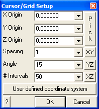
Setup the cursor/grid location, spacing and orientation.
X, Y and Z Origin - specifies the coordinates of the centre of the grid.
Pick - activates the cursor cross-hairs allowing interactive selection of the cursor/grid base from the model. Spacing - specifies the distance between grid points. Angle - specifies the angle (in degrees) between the radii of the cylindrical grid.
# Intervals - specifies the number of grid points that will be displayed.
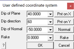
The user defined coordinate system is only active with rectangular and circular grid snapping ( The user defined plane is specified by its dip (φ), dip direction (ϑ) and rake (α) such that:
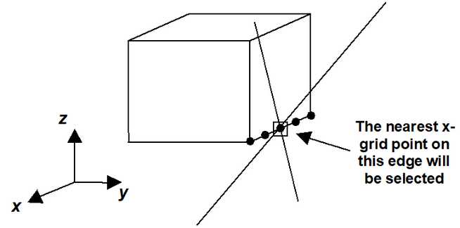
•Pnt on X - The local x-axis (x') is defined along the strike of the plane. A point on this axis can be selected using this function. •Pnt on Y - The local y-axis (y') is defined as down dip. A point on this axis can be selected using using this function. •The local z-axis is perpendicular to the plane. •Norm - activates the cursor allowing interactive selection of a surface to make the local UCS plane parallel to. The dip and dip direction of the plane will be set normal to the selected surface. •Rake - allows for rotation of X' around the local z-axis.
For an example on the use of grid snap mode in model building refer to
|