![]() Plot > Strength Factors > SF-C Strength/Stress
Plot > Strength Factors > SF-C Strength/Stress
![]() Plot > Strength Factors > SF/C Stress/Strength
Plot > Strength Factors > SF/C Stress/Strength
![]() Plot > Strength Factors > Δτmax Excess Stress
Plot > Strength Factors > Δτmax Excess Stress
![]() Plot > Strength Factors > Δτoct Excess Stress
Plot > Strength Factors > Δτoct Excess Stress
|
|
Top Previous Next |
|
Contours the excess shear stress or strength factor using method "C". These components can be accessed via the Strength Factor Components toolbar as follows:
This toolbar can be changed to a vertical orientation by dragging is against either the right or left hand edge of the main window. It can be changed back to a horizontal orientation by dragging is against either the top or bottom edge of the main window.
Selecting the
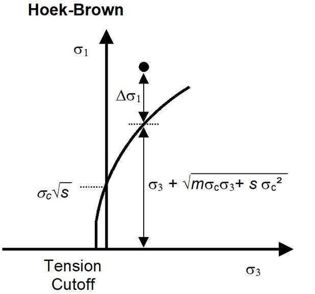
In elastic analysis the major and minor principal stresses can be used with the Mohr-Coulomb or Hoek-Brown strength criteria
to estimate the amount of damage due to over-stressing. Since none of the parameters have any orientation sensitivity, this criterion is representative for homogeneous rock mass stability.
By contrast, in non-linear analysis the stresses can never exceed the strength unless some creep is used. In this latter case, viscous creep can allow stress states above the failure criterion, thus indicating a lack of static equilibrium. Hence for non-linear analysis one normally directly considers the amount of non-linear strain or the strain rate predicted by the model
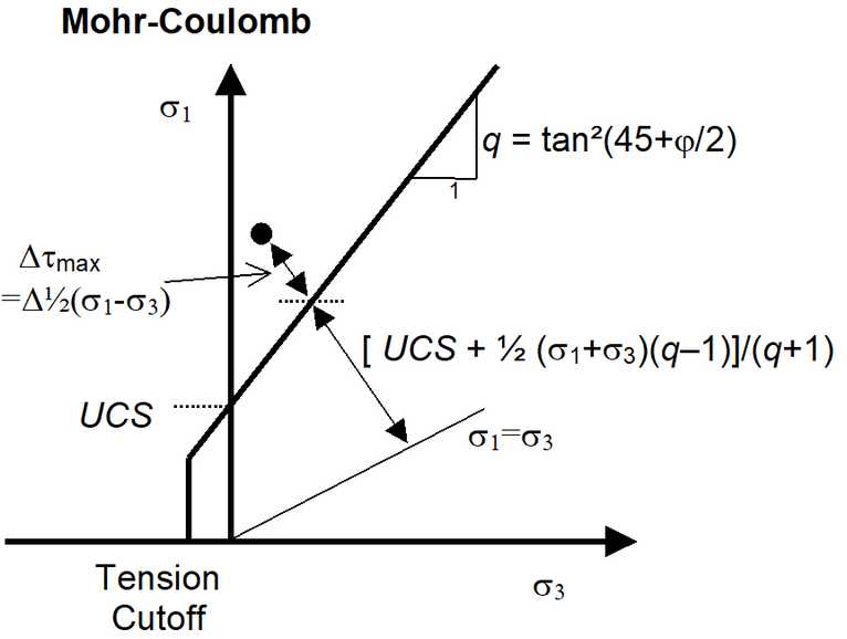
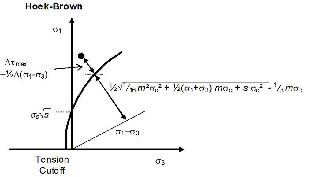
Method "C" assumes that the stress path to failure takes place by increasing σ1 while loosing confinement. This is representative of an abutment failure where σ1 - σ3 is considered to be the driving force.
Δτmax = ½(σ1 - σ3) - [ UCS + ½(σ1+σ3) (q-1) ]/(q+1) = [σ1 - ( UCS + q σ3) ]/(q+1)
Δτmax = ½(σ1 - σ3) - ½{ √[ 1/16 m²σc² + ½(σ1 + σ3) mσc + s σc²] - ¼ mσc }
where q = tan²(45+φ/2) τoct = ¹/3 √[( σ1 - σ2 )² + ( σ2 - σ3 )² +( σ3 - σ1 )²] σmean = ¹/3 ( σ1 + σ2 + σ3 )
Note that the strength parameters have been chosen so that the criterion simplifies to the Mohr-Coulomb criterion when σ2 equals σ3.
Strength parameters are setup using
Related topics:
|