![]() Plot > Strength Factors > SF-ub Strength/Stress
Plot > Strength Factors > SF-ub Strength/Stress
![]() Plot > Strength Factors > SF/ub Stress/Strength
Plot > Strength Factors > SF/ub Stress/Strength
![]() Plot > Strength Factors > Δτub Excess Stress
Plot > Strength Factors > Δτub Excess Stress
![]() Plot > Strength Factors > N(Δτub/std) Probability
Plot > Strength Factors > N(Δτub/std) Probability
UB# Plot > Strength Factors > UB#
|
UB# Plot > Strength Factors > UB# |
Top Previous Next |
|
Contours the strength for ubiquitous-plane shear. These components can be accessed via the Strength Factor Components toolbar as follows:
This toolbar can be changed to a vertical orientation by dragging is against either the right or left hand edge of the main window. It can be changed back to a horizontal orientation by dragging is against either the top or bottom edge of the main window.
Selecting the
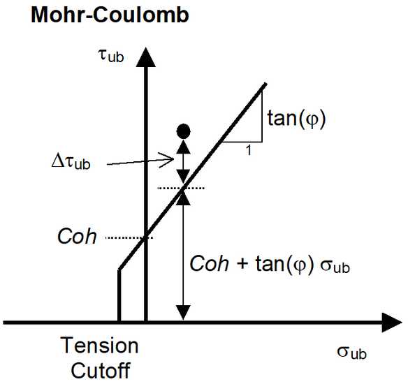
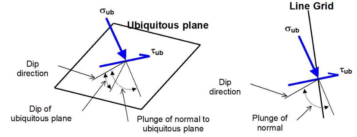
To calculate the ubiquitous shear and normal stresses, the stress state at each point on the grid plane is reoriented to determine the maximum shear stress parallel to the ubiquitous shear plane and the stress normal to the ubiquitous shear plane.
The orientation of the ubiquitous shear plane is set using
In elastic analysis the maximum ubiquitous-plane shear and normal stress can be used with the Mohr-Coulomb strength criterion to estimate the amount of slip due to over-stressing, on a fault, joint set or bedding plane at the specified orientation. Since these parameters are orientation dependant, this criterion is representative for anisotropic rock mass stability.
By contrast, in non-linear analysis the stresses can never exceed the strength unless some creep is used. In this latter case, viscous creep can allow stress states above the failure criterion, thus indicating a lack of static equilibrium. Hence for non-linear analysis one normally directly considers the amount of non-linear strain or the strain rate predicted by the model
Backfill-Hyperbolic in DD planes
Here we assume that the stress path to failure takes place by increasing tub without loosing confinement.
Strength parameters are set up using
Related topics:
UB#2 & UB#3 – activates strength parameters for ubiquitous plane #2 and/or #3. When checked, the minimum for all active ubiquitous planes is presented for all strength parameters ( |