![]() CAD > Build > Grid Line
CAD > Build > Grid Line
|
|
Top Previous Next |
|
Builds a grid line. Analysis results (stresses, strains and displacements) are calculated on these grid lines. Each grid line will be further subdivided at a later stage in the program. This function uses the same construction functionality as Note that grid planes can be created using
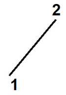
When the routine is initiated the user is prompted to select multiple corners that define points along the grid line. The grid line is considered to be complete when either the final corner is selected twice or the user selects
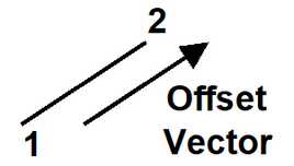
After the first point has been entered, the remaining point can be generated by offsetting
The coordinates of the corners can be typed in from the keyboard
selected by freehand drawing, picked from other entities (other blocks or construction lines) or digitized
A large variety of drawing tools are available to assist in visually selecting points from the model
Corners can be unselected using
Corners can be reselected using
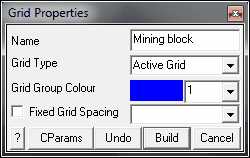
Upon completion of grid plane construction the user is prompted to enter the properties. This allows you to specify a name for the grid line.
Name - specifies a descriptive name for the grid.
Grid Type - specifies whether you want the grid to be active (used in the stress analysis) or inactive (not used in the stress analysis).
Fixed Grid Spacing - specifies the user grid spacing.
This parameter can be used to force uniform discretization on selected grids. Extreme caution should be used in specifying this value since a small value can easily lead to enormous problem size.
In general this option should not be used (unchecked) and discretization should be left to the AG parameter. This latter parameter will concentrate elements only where analysis results are requested thus optimizing the use of elements and minimizing problem size.
CAD > Properties Control Parameters
Undo - unselects the last point entered and returns to the grid construction routine
Build - completes grid construction and enters the block into the model database.
Once you have completed this operation you have one last chance to undo this and remove this grid from the model database by selecting
Cancel - aborts grid construction.
For examples on the use of field point grid planes refer to:
Pressing the space-bar automatically activates the last build function that was used.
|