![]() CAD > Edit > Smooth Construction Lines
CAD > Edit > Smooth Construction Lines
|
|
Top Previous Next |
|
Smooths construction lines by eliminating corner points (also see
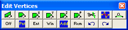
This routine can be initiated either by picking the When you initiate this routine you will first be prompted to build a list of vertices that you wish to smooth.
•If Tools > Shift-key Selection is checked, you must hold down the Shift-key to make multiple selections. •By default, selected entities are added to the list, however if the Ctrl-key is held down, selected entities will be removed from the list. •While holding down the Shift-key or Ctrl-key, you can drag open a crossing window. •Use of this toolbar is detailed in Build A List of Vertices for Editing •Pressing the space-bar automatically activates the last edit function that was used. •Holding the Alt-key when you right-click automatically repeats the last edit function that was used.
Once you have selected the desired entities, you can either pick any of the edit buttons:
•double click on any vertex to execute the highlighted function, •right click for a list of options.
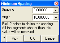
The Spacing value limits the minimum space between points. For example if the Spacing was specified as 2m and the trace length between points 4 and 5 in the following figure was 1.5m, point 4 would be removed and replaced by a straight line between points 3 and 5.
A zero value for this parameter indicates that it will not be used.
The Angle value limits the minimum angle between successive line segments. For example if the Angle was specified as 10° and the direction of line segment 3-4 was 7° different than the direction of line segment 4-5 in the following figure, point 4 would be removed and replaced by a straight line between points 3 and 5.
A zero value for this parameter indicates that it will not be used.
OK - completes editing of the offset vector and stretches the selected vertices.
Cancel - aborts stretching of vertices.
Once you have completed any edit operation you have one chance to undo the modifications by selecting
You can also restore the same selection set and modify the same set of entities again be selecting
You can adjust the double click time using
Notes:
•The location of all points along construction lines can be viewed by setting the View > Render > Cline dot radius parameter. •Before using this trace smoothing function, construction lines should be cleaned up using the CAD > Pack and Renumber Clines function. •You can adjust the double click time using Tools > Double Click Time.
|