![]() CAD > Edit > Stretch
CAD > Edit > Stretch
|
|
Top Previous Next |
|
Adds an offset to selected vertices.
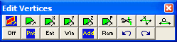
This routine can be initiated either by picking the When you initiate this routine you will first be prompted to build a list of vertices that you wish to stretch
•If Tools > Shift-key Selection is checked, you must hold down the Shift-key to make multiple selections. •By default, selected entities are added to the list, however if the Ctrl-key is held down, selected entities will be removed from the list. •While holding down the Shift-key or Ctrl-key, you can drag open a crossing window. •Use of this toolbar is detailed in Build A List of Vertices for Editing •Pressing the space-bar automatically activates the last edit function that was used. •Holding the Alt-key when you right-click automatically repeats the last edit function that was used.
Once you have selected the desired entities, you can either pick any of the edit buttons:
•double click on any vertex to execute the highlighted function, •right click for a list of options.
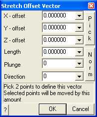
X, Y and Z – offset specify the components of the stretch vector. •All selected vertices will be moved to the location specified by this offset. •This requires that you select two points to define this vector. •Once selected, the components of the offset vector are displayed in the dialogue box.
Pick activates the cursor cross-hairs allowing interactive selection of the offset vector from the model. This requires that you select two points to define this vector.
Length, Plunge and Direction - specify the components of the offset vector. All selected vertices will be moved by this amount.
Norm - activates the cursor allowing interactive selection of a surface to make the offset vector normal to.
To assist in visually selecting points from the model, all snap functions are available.
Once selected, the components of the offset vector are displayed in the dialogue box.
OK - completes editing of the offset vector and stretches the selected vertices.
Cancel - aborts stretching of vertices.
Once you have completed any edit operation you have one chance to undo the modifications by selecting
You can also restore the same selection set and modify the same set of entities again be selecting
You can adjust the double click time using
|